4-bit angle modulating 16 LEDs using Arduino and shift registers
So in this article we’re extending the previous example where we learned how to drive 16 LEDs using three pins of the Arduino. This time we’re taking it to the next level and learn how we can apply fading effects to individual LEDs by using Bit Angle Modulation.
Pulse Width Modulation
Bit Angle Modulation or BAM is very similar to Pulse Width Modulation (PWM) which is supported on the Arduino by default by using the PWM pins, which are marked with a tilde (~). PWM allows you to just analogWrite(); a value ranging from 0 to 255 to the specified pin, and Arduino will take care of the rest. If you connect a volt-meter to the output pin you would see a voltage between 0V and 5V.
PWM actually applies a squarewave to the pin where it switches from 5V (high) to 0V (low) and back, very rapidly. The period where the pin is high in relation to the total time of one cycle, is called the duty cycle. The duty cycle is at the core of PWM and is being used to control the exact overall voltage of the pin.
Explaination of PWM on arcuino.cc
As the image above shows us; a 0% duty cycle means that the pin is low for the full cycle, whereas a 100% duty cycle means the pin is high for the full cycle, no rocket science there. It is only where the duty cycle ranges between 0% and 100%, it is starting to get interesting.
A duty cycle of 50% means that the pin is high only for the first half of the cycle, and then low for the remainder of the cycle, only to start over again at the beginning of the new cycle.
If we connect a LED to the pin, it actually starts to flicker since it lights up when the pin is high and turns on when the pin is low. The key to this is to do it so fast that it isn’t distinguishable by the human eye, instead we’ll see a dimmer LED.
How is Bit Angle Modulation different?
Ok, so by now we know that the brightness of a LED can be controlled by switching it on and off very rapidly. In the part above we’ve read about how this is actually done using PWM, but Bit Angle Modulation or BAM is just another method to achieve the same thing.
The key difference between PWM and BAM is in how the high versus low periods are calculated. Bit Angle Modulation is also referred to as Binary Code Modulation and as the name suggest; we need to start thinking in binary. BAM uses the key property of binary numbers where as you count upwards, the value of the bits doubles in value. So the least significant bit is 1 and the most significant bit (in a 4-bit system) is 8.
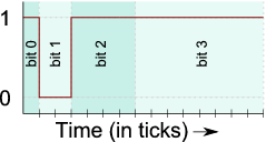
This article on batsocks.co.uk gave me a clear understanding of how this would actually apply to modulation: The first bit in the example is 1 so the pin will be high for one tick (CPU cycle). The next bit is 0 so the pin will be low for two ticks. The next bit is 1 so the pin will be high again for four ticks and the last bit is also a 1 so the pin will continue being high for another eight ticks. See? As the position of the bit in the binary system determines its value, it is determining the amount of ticks it will applying its value for in BAM.
Using BAM we can actually write these values as decimal ranging from 0–15. Since 15 in decimal is 1111 in binary. This would corespondent to a 100% duty cycle in PWM meaning the LED would be turned on with its full brightness.
The Code
Now we understand how PWM and BAM actually work and how they achieve their similar goals very differently it is time to look at some code.
 1#include <SPI.h>
 2
 3// define pins and other variables
 4const int latchPin = 8;
 5const int clockPin = 13;
 6const int dataPin  = 11;
 7const int NUMBER_OF_CONNECTED_LEDS = 16;
 8
 9// global array that keeps track of the LEDs brightnesses
10bool brightnessMask[NUMBER_OF_CONNECTED_LEDS*4];
11
12// NOTE: some methods are omitted for clarity
13
14/////////////////
15// BAM methods //
16/////////////////
17
18// convert brightness to bitmasked brightness
19void led(int ledNr, int brightness){
20  // ensure 4-bit limited brightness
21  brightness = constrain(brightness, 0, 15);
22
23  // turn 4-bit brightness into brightness mask
24  for (int i = 3; i >= 0; i--) {
25    if (brightness - (1 << i) >= 0) {
26      brightness -= (1 << i);
27      brightnessMask[(ledNr*4)+i] = 1;
28    }
29    else{
30      brightnessMask[(ledNr*4)+i] = 0;
31    }
32  }
33}
34
35// transform brighnesses to 4-bit BAM
36void refresh(){
37  // Loop over each LED
38  for (int cycle = 0; cycle < 16; cycle++) {
39    for (int currentLed = 0; currentLed < NUMBER_OF_CONNECTED_LEDS; currentLed++) {
40      int maskPosition = currentLed * 4;
41      if (cycle == 1 && brightnessMask[maskPosition]) {
42        turnOnLed(currentLed);
43      }
44      else if ((cycle == 2 || cycle == 3) && brightnessMask[maskPosition+1]) {
45        turnOnLed(currentLed);
46      }
47      else if (cycle >= 4 && cycle <= 7 && brightnessMask[maskPosition+2]) {
48        turnOnLed(currentLed);
49      }
50      else if (cycle >= 8 && cycle <= 15 && brightnessMask[maskPosition+3]) {
51        turnOnLed(currentLed);
52      }
53      else{
54        clearLeds();
55      }
56    }
57  }
58  clearLeds();
59}
On line 10 we’re keeping track the brightness of each connected LED using big array called brightnessMask. I couldn’t find a way to create multidimensional arrays in Arduino so I ended up making one big array with the length of four times the number of connected LEDs; four bits for each connected LED.
On line 19 I’ve modified the led() method so it also accepts the brightness of the LED and added some logic which converts a decimal number (0–15) to a 4-bit binary value which get saved in the brightnessMask array afterwards.
The real Bit Angle Modulation magic happens in the refresh() method that starts on line 36. As you see it consists of two loops; the first loop simply loops 15 times, equal to the number of ticks in one 4-bit cycle. The second loop simply iterates over each connected LED in our project.
The first thing that happens within that inner loop is getting the index reference of the first bit for the current LED in the brightnessMask. What follows is basically a series of if-statements checking wether the LED in the current cycle should be turned on or off depending on the boolean in the brightnessMask.
The rest of the code is untouched. The turnOnLed() method is still the same where it shifts out a value to turn on the selected LED and the clearLeds() method still shifts out all zeroes so all LEDs turn off again.
That’s it! This is all we have to do to make Bit Angle Modulation work on an Arduino using shift registers.
Thanks for reading!