Driving 16 LEDs using only three pins of an Arduino
It has been quite a while since I last played with the Arduino so I figured it was about time to do so. In this article I’ll show you how you can drive 16 LEDs with two 8-bit shift-registers using only three pins of the Arduino. So lets get started!
Parts list
For this build we’re using the following parts:
- Arduino UNO (any Arduino will do actually)
- Breadboard (with at least 32 rows to fit the components)
- 16 x LEDs
- 16 x resistors (220 Ohm)
- 2 x 74HC595 shift-registers
- Enough jumper wires to tie it all together
Schematic
The wiring for this build is actually pretty simple. I’ve created a little schematic using 123d-circuits.io to explain things in a little more detail. (Unfortunately 123d-circuits.io is no longer available)
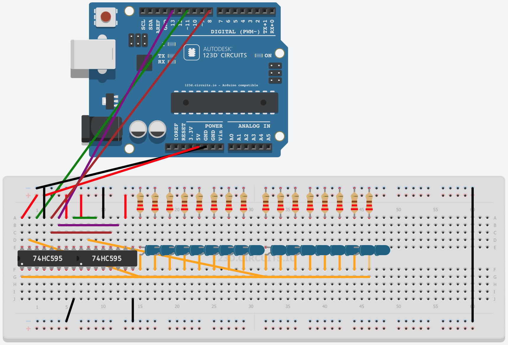
Schematic built with 123d.circuits.io
In this schematic the black wires are tied to GND. The red wires are 5V and the orange wires are all connections from the 2 74HC595 shift-registers terminals (Q0-Q7) to the LEDs. The wires connected to the Arduino are the data-line (green), the clock line (purple) and the latch line (brown) as well as GND and power.
As you might have noticed, there are also a couple of connections running from the left shift-register to the right one. The clock and latch pins are simply tied together as a bus. The green one is another story; the data-out from the left shift-register is connected to the data-in of the right shift-register so once we’ve filled our first shift register with 8 bits, we can continue shifting data to the second shift register.
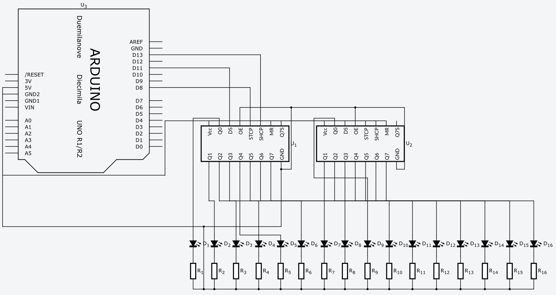
For a more in depth wiring schematic; I’ve spend some time laying out the components in the schematic view:
Schematic view
Wiring
The 74HC595 and addressing the LEDs
The 74HC595 is basically a serial-to-parralel converter where we can convert 8 bits at once. We can push numbers to the shift registers in serial, which get converted to their parrallel binary representation on the output pins. So basically all the LEDs are addressable by counting in binary from 0 to 256.
Pushing a 1 will light up the first LED. Pushing a 2 will light up the second LED. This can be repeated for 4, 8, 16, 32, 64, 128 and 256. The notation for this can be made much easier using bit-shifting (hey! Coincidence?). Using bit-shifting the first LED is addressable by using 1 << 0 (= 1), the second one by using 1 << 1 (=2). This can be repeated for 1 << 3, 1 << 4 … 1 << 8 (=256).
Using shift-registers with Arduino
This sounds very difficult, luckily it isn’t at all! Arduino was kind enough to provide us with the SPI-library which is basically meant to do things like this.
 1#include <SPI.h>
 2
 3// define pins and other variables
 4const int latchPin = 8;
 5const int clockPin = 13;
 6const int dataPin  = 11;
 7
 8// setup the correct pins and initialize SPI library
 9void setup() {
10  // setup pins
11  pinMode(latchPin, OUTPUT);
12  pinMode(clockPin, OUTPUT);
13  pinMode(dataPin,  OUTPUT);
14
15  // setup SPI library
16  SPI.setBitOrder(MSBFIRST);
17  SPI.setDataMode(SPI_MODE0);
18  SPI.setClockDivider(SPI_CLOCK_DIV2);
19  SPI.begin();
20}
21
22void loop() {
23  for(int i =0; i < 16; i++){
24    turnOnLed(i);
25  }
26}
27
28// turn on correct LED using 595's
29void turnOnLed(int ledNr) {
30  digitalWrite(latchPin, LOW);
31
32  if (ledNr >= 8) {
33    SPI.transfer(1<<ledNr-8);
34    SPI.transfer(0);
35  }
36  else {
37    SPI.transfer(0);
38    SPI.transfer(1<<ledNr);
39  }
40
41  digitalWrite(latchPin, HIGH);
42}
43
On the first line we’re just importing the SPI library and we’re defining a couple of pins to be used by the SPI library. The hardware inside the Arduino UNO presets the data and clock pin but luckily the documentation explains this in great detail.
In the setup() function we’re setting up a couple of defaults. Starting on line 16 we’re setting the BitOrder to Most Significant Bit First (MSBFIRST), we’re setting the DataMode (which defines how the clockline should behave) and defining the ClockDivider (which sets the speed at which data gets shifted out). Lastly we’re calling SPI.begin() to tell the Arduino we’d like to start transferring data.
I’ve written another function called turnOnLed() which is responsible for translating the LED numbers (0–15) to their bitshifted values and transferring them using the SPI library.
When you take a closer look at the code inside the turnOnLed() function, you’ll see that I’m checking wether the LED number I’d like to address is greater than or equal to eight. When it is, I’m transferring a zero to the first register (setting all pins low), subtracting 8 from the value (since we start counting from zero again for the second shift register) and transfer the remaining value to the second shift register.
At last in the loop() function, we’re just looping over all the LEDs by counting from 0 to 15 and calling the turnOnLed() function and passing in that number. Each time the loop() function gets called all the LEDs will individually light up, bit since we’re not using any delays here, it’ll look like all the LEDs are lit at once. Adding a half second delay in the loop will make a cool little looping animation.
So that’s it! We’ve covered how to wire 16 LEDs to one Arduino using only three pins and we’ve covered the basics of bitshifting and using the SPI library to address all the LEDs.
Try it out and let me know what you’ve built with it. In the next part I’ll be showing how you can extend this example to support 4-bit angle modulation so we can fade the LEDs individually and make some cool animations.