Building a 4x4x4 LED Cube. Part I; The hardware
As you might have read in my previous posts I’ve been fiddling around with an Arduino and a couple of LEDs using shift registers. I’ve explained how you can control 16 LEDs using only three pins of an Arduino and in a more recent post I’ve talked about Bit Angle Modulation to apply fading effects to individual LEDs in the 16 LED array. In this post I’ll go more into detail on how you can setup a 4x4x4 LED cube.
The cube
As the name might suggest a 4x4x4 cube is a LED cube that consists of four layers in height with each layer containing 4x4 LEDs. So each layer has 16 LEDs which brings the total LEDs we need to control to 64!
The build of the LED Cube itself is fairly easy. You’d just need to solder four grids of 4x4 LEDs together making sure to connect the cathodes (negative leads) of the LEDs together. When you have four of these LED grids, stack them on top of eachother and solder the anodes (positive leads) together vertically, making 16 columns. This part can get a little tricky since the parts tend to move while soldering ;)
Schematic wise it looks like shown below, where every cathode of each layer and all anodes of all columns are soldered together.
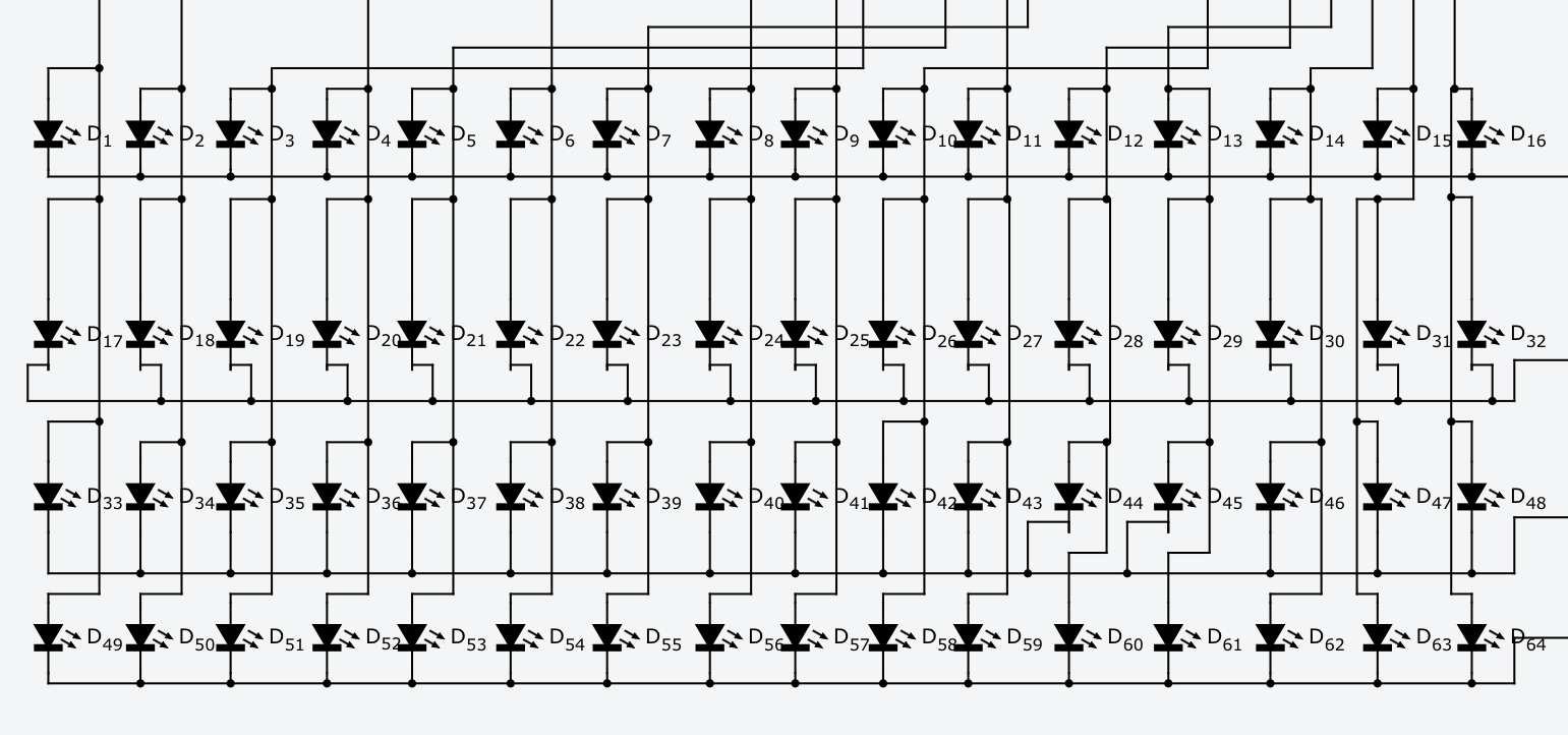
Schematic drawn using 123d.circuits.io
In the end the cube has 16 connections to control the anodes and four connections to control the cathodes. Looking at the schematic for the driver below will give a clear overview of how these work together.
The driver
To drive this amount of LEDs I’ve created a driver which consists of three 595 shift registers, four NPN transistors and 20 resistors.
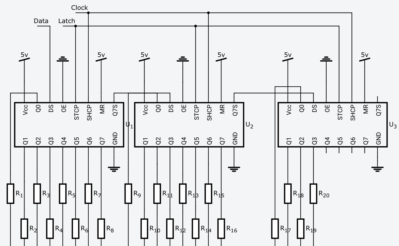
Schematic drawn using 123d.circuits.io
As shown above the three shift registers are chained so the total number of output pins is be increased to 24. Only 20 of them are used, where the first 16 are connected to 220-Ohm resistors (R1-R16) before connecting to the anode columns. The last shift register is connected to four 10k-Ohm resistors which in their turn are connected to four NPN transistors.
Schematic drawn using 123d.circuits.io
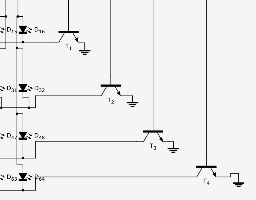
The NPN transistors are put in place to select which layer we’re controlling so by pulling one of the transistors high, we’re closing the circuit for that given layer enabling the LED to light up. Selecting which led of the layer that is, is done by simply pulling the entire column high.
That’s it for this one! The full schematic can be found here. Enjoy! Unfortunately the schematic isn’t available online anymore :-(